Introduction to Car Engines
For many, a car is a daily necessity, transporting us to work, family, and adventures. Yet, beneath the hood lies a complex system, the engine, often a mystery to the average driver. Understanding the basics of your car engine isn’t just for mechanics; it empowers you with knowledge about your vehicle’s core functionality. This article serves as your comprehensive guide to car engine parts and what they do, breaking down the intricate world under the hood into digestible information. We’ll explore the essential components of the internal combustion engine, the powerhouse that drives most vehicles on the road today, and shed light on their individual roles in making your car move.
The Heart of Your Vehicle: Understanding the Internal Combustion Engine
The term “internal combustion engine” might sound technical, but the concept is quite straightforward. It’s an engine where the magic of power generation happens inside. Fuel and air are mixed and combusted within the engine itself, creating energy that sets the pistons in motion. This motion, in turn, is converted to power that propels your car. This contrasts with “external combustion engines,” like steam engines, where fuel is burned outside the engine to heat water and create steam, which then drives the engine.
Interestingly, while steam engines are often associated with the early days of mechanized movement, internal combustion engines actually predate them. Early iterations of internal combustion engines emerged in the 16th century, experimenting with gunpowder as fuel. These were rudimentary “atmospheric engines” relying on vacuum creation after a gunpowder explosion to move a piston. However, they were inefficient and soon overshadowed by the promising advancements in steam engine technology.
It wasn’t until 1860 that a practical and reliable internal combustion engine was invented by Jean Joseph Etienne Lenoir. His engine used natural gas ignited by a flame, marking a significant step forward. Building on Lenoir’s work, Nicolaus August Otto, in 1876, developed the four-stroke engine. Otto’s invention revolutionized engine technology, and its fundamental design remains the blueprint for car engines even today. The four-stroke engine’s efficiency and power paved the way for the modern automotive era.
Anatomy of a Car Engine: Key Components and Their Functions
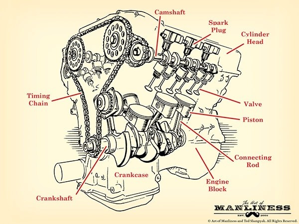
To understand how a car engine works, it’s crucial to familiarize yourself with its main parts. Think of it like learning the different organs of the human body – each component has a vital role to play in the engine’s overall function. Let’s delve into the anatomy of a typical car engine and explore the function of each key part.
Engine Block (Cylinder Block)
The engine block, also known as the cylinder block, is the foundational structure of the engine. Imagine it as the skeleton upon which all other engine parts are built. Typically cast from aluminum alloy for its lightweight properties, though some manufacturers still utilize iron for its durability, the engine block’s primary feature is its cylinders. These are cylindrical cavities precisely bored into the block where the pistons move up and down. The number of cylinders directly correlates with engine power; generally, more cylinders mean a more powerful engine. Beyond housing cylinders, the engine block also incorporates intricate ducts and passageways for the circulation of engine oil and coolant. These internal channels are crucial for lubricating moving parts and dissipating heat, ensuring the engine operates within safe temperature limits and preventing wear and tear.
Why is an engine called a “V6” or “V8”?
This nomenclature refers to the cylinder configuration and count within the engine block. In a four-cylinder engine, cylinders are often arranged in a straight line above the crankshaft, forming an inline engine. Another four-cylinder arrangement is the flat-four, where cylinders are horizontally opposed in two banks.
Engines with more than four cylinders often adopt a V-shaped configuration. Here, cylinders are divided into two banks, creating a “V” shape when viewed from the front or rear. A V6 engine has six cylinders distributed across these two banks (three per bank), while a V8 engine has eight cylinders (four per bank). This V-configuration is a compact way to package more cylinders, contributing to increased power output while fitting within the engine bay.
Combustion Chamber
The combustion chamber is where the engine’s power is born. This is the space where fuel and air mix under pressure and are ignited by a spark, resulting in a controlled explosion that drives the pistons. The combustion chamber isn’t a separate component but rather a space formed by three key parts: the cylinder walls, the piston top (acting as the chamber’s floor), and the cylinder head (serving as the ceiling). Precise design and sealing of the combustion chamber are critical for efficient combustion and maximizing power output.
Cylinder Head
The cylinder head is a complex component made of metal, typically aluminum or cast iron, that seals the top of the engine cylinders, effectively closing the combustion chamber. The underside of the cylinder head is often cast with indentations or specifically shaped volumes that contribute to the combustion chamber’s final shape and optimize combustion. A crucial element for sealing the combustion chamber and preventing leaks between the cylinder block and cylinder head is the head gasket. This gasket is sandwiched between the cylinder head and engine block, creating a pressure-tight seal even under extreme engine conditions. Furthermore, the cylinder head serves as the mounting point for several critical components, including intake and exhaust valves, spark plugs, and fuel injectors. These components are strategically positioned within the cylinder head to facilitate the intake of air and fuel, ignition, and exhaust of combustion gases.
Piston
Pistons are cylindrical components that move vertically within the engine cylinders. Resembling inverted soup cans in shape, pistons are driven by the force of combustion within the combustion chamber. When the air-fuel mixture ignites, the expanding gases exert pressure on the piston head, forcing it downwards. This linear motion of the piston is then converted into rotational motion by the crankshaft. Each piston is connected to the crankshaft via a connecting rod (often called a “con rod”). The connection involves a piston pin that joins the piston to the connecting rod and a connecting rod bearing that allows the connecting rod to rotate smoothly on the crankshaft. Around the top circumference of each piston are grooves that house piston rings. These rings are vital for sealing the combustion chamber and controlling oil. Typically, a piston has compression rings located in the top grooves. These rings press outwards against the cylinder walls, creating a tight seal to prevent combustion gases from escaping past the piston. The oil ring, situated in a lower groove, serves to scrape excess oil from the cylinder walls as the piston moves, preventing oil from entering the combustion chamber and also returning this oil to the crankcase for recirculation.
Crankshaft
The crankshaft is the backbone of the engine’s power delivery system. Its primary function is to convert the reciprocating (up-and-down) motion of the pistons into rotary motion – the kind of motion needed to turn the wheels of your car. The crankshaft is a robust component that runs lengthwise within the engine block, typically positioned near the bottom. Extending from the front to the rear of the engine, the crankshaft connects to various systems. At the front end, it usually drives belts that power components like the camshaft and other engine accessories. At the rear end, it connects to the drivetrain, which transmits power to the wheels. To prevent oil leaks where the crankshaft exits the engine block, oil seals or O-rings are used at both ends.
The crankshaft operates within the crankcase, the lower section of the engine block, which provides protection from external debris. The very bottom of the crankcase forms the oil pan, which serves as a reservoir for the engine oil. Inside the oil pan, an oil pump draws oil and pushes it through an oil filter to remove contaminants. This filtered oil is then distributed throughout the engine, lubricating critical components such as the crankshaft bearings, connecting rod bearings, and cylinder walls. After lubricating these parts, the oil drains back into the oil pan, completing a continuous lubrication cycle. To ensure smooth operation and minimize vibrations, balancing lobes or counterweights are integrated into the crankshaft design. These counterweights offset the forces generated by the pistons and connecting rods, reducing engine vibration and preventing damage. The crankshaft rotates within main bearings, which provide smooth, low-friction support between the crankshaft and the engine block, allowing for free rotation.
Camshaft
The camshaft can be considered the engine’s brain, precisely controlling the timing of valve operation. It works in sync with the crankshaft, typically connected via a timing belt or timing chain, ensuring that the intake and exhaust valves open and close at precisely the right moments in the engine’s cycle. The camshaft features egg-shaped protrusions called lobes or cams along its length. As the camshaft rotates, these lobes actuate the valves. In most engines, the camshaft is positioned in the upper part of the engine block, often above the crankshaft. Inline engines typically use a single camshaft to control both intake and exhaust valves. V-shaped engines, however, may employ two or even four camshafts. Engines with two camshafts, often called dual overhead cam (DOHC) engines, can have one camshaft dedicated to intake valves and the other to exhaust valves for each cylinder bank. Some advanced V-engines utilize quad overhead cams (QOHC), featuring two camshafts per cylinder bank, further optimizing valve control.
Timing System
The timing system is essential for synchronizing the movements of the crankshaft and camshaft. This synchronization is achieved using a timing belt or timing chain, which physically links the crankshaft and camshaft gears. The timing belt/chain ensures that the camshaft rotates at a precise ratio relative to the crankshaft, maintaining the correct valve timing throughout engine operation. If the timing between the crankshaft and camshaft is disrupted, for instance, if the timing belt skips a tooth or breaks, the engine’s valve timing will be thrown off. This loss of synchronization can lead to severe engine malfunctions, preventing the engine from running and potentially causing internal damage due to collisions between pistons and valves.
Valvetrain
The valvetrain is the mechanical system responsible for operating the engine’s valves. Mounted within the cylinder head, the valvetrain precisely controls the opening and closing of the intake and exhaust valves. Key components of the valvetrain include the valves themselves, rocker arms, pushrods (in some engine designs), and lifters (also known as valve tappets). These parts work together to translate the rotational motion of the camshaft lobes into the linear motion required to open and close the valves at the correct times.
Valves (Intake & Exhaust)
Valves are critical components that regulate the flow of gases into and out of the combustion chamber. There are two main types: intake valves and exhaust valves. Intake valves are responsible for allowing the air-fuel mixture to enter the combustion chamber at the beginning of the combustion cycle. Exhaust valves then open to release the burnt gases, or exhaust, from the combustion chamber after combustion has occurred. The number of valves per cylinder can vary. Most engines have at least one intake and one exhaust valve per cylinder. However, multi-valve engines, especially in performance vehicles, often feature four valves per cylinder (two intake and two exhaust). Some engines even use three valves per cylinder (two intake, one exhaust). Multiple valves per cylinder improve engine “breathing,” allowing for more efficient intake and exhaust flow, which translates to better engine performance and power output.
Rocker Arms
Rocker arms are lever-like components within the valvetrain that mediate between the camshaft lobes and the valves. Each rocker arm pivots on a fulcrum point. One end of the rocker arm contacts a camshaft lobe, while the other end presses down on the valve stem. As the camshaft rotates, the lobe pushes on one end of the rocker arm, causing the other end to move in the opposite direction and open the valve. This see-saw motion efficiently translates the rotary motion of the camshaft into the linear motion needed to operate the valves. Rocker arms are used in various valvetrain configurations, including both overhead valve (OHV) and some overhead camshaft (OHC) engines.
Pushrods/Lifters
Pushrods and lifters are components used in overhead valve (OHV) engine designs. In OHV engines, the camshaft is located in the engine block, below the cylinder head. In this configuration, the camshaft lobes cannot directly actuate the rocker arms, which are located in the cylinder head. Lifters, also known as valve tappets, are positioned between the camshaft lobes and pushrods. As the camshaft rotates, the lobes move the lifters upwards. This upward motion is then transmitted through the pushrods to the rocker arms in the cylinder head. The pushrods act as connecting rods, transferring the camshaft’s motion upwards to actuate the rocker arms and open the valves. In overhead camshaft (OHC) engines, the camshaft is located in the cylinder head, directly above the valves, often eliminating the need for pushrods. In OHC designs, the camshaft lobes may directly actuate rocker arms or directly act on lifters that then actuate the valves.
Fuel Injectors
Fuel injectors are precision components responsible for delivering fuel into the engine’s cylinders for combustion. Before the widespread adoption of fuel injection in the 1980s, carburetors were the primary fuel delivery system. Modern cars almost universally use fuel injection systems, which offer more precise fuel control, improved fuel efficiency, and reduced emissions compared to carburetors. There are three main types of fuel injection systems commonly used in cars: direct fuel injection, ported fuel injection, and throttle body fuel injection.
Direct fuel injection (DFI) systems inject fuel directly into the combustion chamber. Each cylinder has its own dedicated injector that sprays a precisely metered amount of fuel directly into the cylinder at the optimal moment for combustion. DFI offers very precise fuel control and can improve fuel efficiency and power.
Ported fuel injection, also known as multi-point fuel injection (MPFI), injects fuel into the intake manifold, just upstream of the intake valves. Each cylinder has an injector positioned to spray fuel into its intake port. When the intake valve opens, the air-fuel mixture is drawn into the combustion chamber. Ported fuel injection is a common and effective system, balancing performance and cost.
Throttle body fuel injection (TBI) is a simpler system with one or two injectors located in the throttle body, above the intake manifold. Fuel is sprayed into the throttle body where it mixes with incoming air before being distributed to all cylinders via the intake manifold. TBI systems are less complex than multiport or direct injection but offer less precise fuel control.
Spark Plug
The spark plug is a critical component for igniting the air-fuel mixture in gasoline engines. Located in the cylinder head, each cylinder typically has at least one spark plug. The spark plug generates an electrical spark within the combustion chamber. This spark ignites the compressed air-fuel mixture, initiating combustion and the power stroke of the engine cycle. The spark must be precisely timed to occur at the optimal point in the engine cycle to ensure efficient and complete combustion.
The Four-Stroke Cycle: Powering Your Car
Now that we’ve explored the individual engine parts, let’s understand how they work together in a coordinated sequence to generate power. The four-stroke cycle is the fundamental process that drives most car engines. This cycle consists of four distinct piston strokes: Intake, Compression, Combustion (Power), and Exhaust. These four strokes occur in sequence within each cylinder, and this cycle is repeated continuously to keep the engine running.
1. Intake Stroke:
- The piston moves downwards in the cylinder.
- The intake valve opens, allowing the air-fuel mixture to be drawn into the combustion chamber.
- This downward movement of the piston creates a vacuum, drawing the air-fuel mixture in.
2. Compression Stroke:
- The intake valve closes.
- The piston moves upwards in the cylinder.
- The air-fuel mixture is compressed into a smaller volume within the combustion chamber.
- Compression increases the temperature and pressure of the mixture, making it more readily combustible.
3. Combustion (Power) Stroke:
- As the piston reaches the top of its compression stroke, the spark plug ignites the compressed air-fuel mixture.
- The combustion of the mixture creates a rapid expansion of hot gases.
- These expanding gases exert pressure on the piston head, forcefully pushing the piston downwards.
- This downward force is transmitted through the connecting rod to the crankshaft, causing the crankshaft to rotate. This is the stroke that generates the engine’s power.
4. Exhaust Stroke:
- The exhaust valve opens.
- The piston moves upwards in the cylinder.
- The upward movement of the piston pushes the burnt exhaust gases out of the combustion chamber through the open exhaust valve.
- This clears the cylinder for the next intake stroke, starting the cycle anew.
This four-stroke cycle occurs in each cylinder of the engine, and these cycles are carefully timed and coordinated to produce a continuous and smooth power output. The crankshaft rotation resulting from the power strokes is then transmitted through the drivetrain to the wheels, propelling the vehicle.
Conclusion: Appreciating the Complexity and Ingenuity of Car Engines
Understanding the intricate workings of a car engine, from the engine block to the spark plugs and the four-stroke cycle, provides a deeper appreciation for the engineering marvel that powers our vehicles. Each part plays a crucial role in converting fuel into motion. While this guide provides a comprehensive overview of car engine parts and their functions, the world of automotive mechanics is vast and continuously evolving. Further exploration into specific engine types, advanced technologies, and engine maintenance can deepen your knowledge and empower you as a car owner. By grasping these fundamentals, you’re no longer just driving a car; you’re understanding the heart that makes it beat.