The Hcu Car Part, or Hydraulic Control Unit, is a critical component in modern vehicle braking systems, particularly in Anti-lock Braking Systems (ABS) and Electronic Stability Control (ESC). As a vital node on a vehicle’s high-speed communication network, information about the HCU can typically be accessed through the OBD-II Diagnostic Link Connector (DLC), making diagnostics more streamlined.
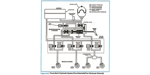
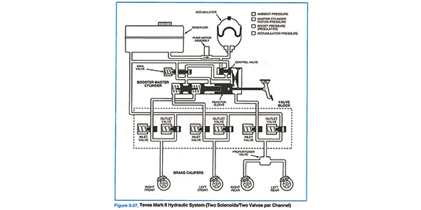
At the core of any ABS or ESC system lies the ABS controller/modulator, also known as the HCU. This unit acts as the central command for managing brake pressure to each wheel. In standard braking situations, the HCU allows pressure from the master cylinder to pass through unchanged, ensuring normal braking functionality.
It’s important to understand that ABS serves as the foundational technology for ESC systems. ESC enhances ABS by integrating sophisticated software and additional sensors. These sensors, such as yaw rate sensors and steering angle sensors, and sometimes even throttle control, work in tandem to maintain vehicle stability and control in challenging driving conditions.
A fundamental four-channel ABS system typically incorporates eight solenoids within the HCU. These are divided into four isolation solenoids and four dump solenoids, allocating two solenoids for each wheel. More complex systems might feature an increased number of solenoids or valves to isolate the master cylinder from the HCU entirely. ESC systems, being more advanced, commonly employ 12 or more solenoids to achieve finer control over braking forces.
How the HCU Operates During Braking Events
To fully grasp the function of an HCU car part, let’s break down its operation during different braking scenarios:
Apply:
During normal braking, when you depress the brake pedal, the master cylinder generates pressure. This pressure travels directly to the wheels because the outlet/dump solenoid within the HCU remains closed. This represents a standard, passive braking event where the HCU facilitates regular brake function.
Hold:
If the ABS system detects that a wheel is beginning to lock up, the HCU immediately responds. The inlet/isolation solenoid for that wheel closes. This crucial action prevents any further pressure from the master cylinder from reaching the affected wheel, allowing the wheel a chance to regain rotational speed.
Release:
Should the wheel persist in locking despite the “hold” action, the outlet/dump valve for that wheel will open. This releases or bleeds off the hydraulic pressure that was causing the wheel to lock. With the pressure relieved, the wheel is now free to rotate, preventing a skid.
Reapply:
Because pressure has been bled off from the master cylinder during the “release” phase, the HCU initiates a “reapply” action. The pump within the HCU activates, building pressure. Simultaneously, the outlet valve closes, and the inlet valve opens. The pump then directs pressure back to the wheel, re-engaging the brake.
This entire cycle of apply, hold, release, and reapply happens incredibly rapidly during ABS activation. The rapid operation of the solenoids and the pump creates the characteristic “kick back” or pulsation felt in the brake pedal when ABS is engaged.
Mechanical Problems with the HCU Car Part
While mechanical failures in the HCU are not frequent, they can occur. Issues often arise from valve seats and pintles becoming stuck or failing to seat correctly. This can be caused by contamination from debris, corrosion, or degraded brake fluid within the system.
-
Stuck Inlet/Isolation Valve (Open): If an inlet/isolation valve becomes stuck in the open position, it typically won’t impact normal braking performance. The problem will only become apparent when the ABS system is activated. A stuck open inlet valve can lead to a “pulling” sensation during ABS operation, as pressure control to that wheel is compromised.
-
Stuck Outlet/Dump Valve (Open): If an outlet/dump valve is stuck open in a specific brake circuit, this can result in a more noticeable “pull” even during regular braking. This occurs because brake pressure is prematurely lost at the affected wheel. Diagnosing this issue can be challenging, as technicians might initially suspect other components like brake hoses or calipers before investigating the HCU.
Electrically Testing HCU Solenoids
Faulty solenoids or pumps within the HCU can sometimes trigger diagnostic trouble codes (DTCs). Each solenoid has a typical resistance range, usually between 2 and 8 ohms. However, accessing individual solenoids for direct testing can be difficult or impossible on some HCU designs.
In these cases, utilizing a scan tool with bidirectional control capabilities can be the most effective method for assessing the condition of the HCU car part. Bidirectional control allows technicians to command the HCU to activate specific solenoids and pumps, enabling them to observe the unit’s response and identify any electrical malfunctions.
The Role of HCU in Electronic Stability Control (ESC)
Vehicles equipped with ESC systems typically have a more complex HCU with 12 or more valves/solenoids. While eight solenoids are dedicated to individual wheel control (as in ABS), the additional four solenoids provide the ESC system with the ability to selectively block off the master cylinder and apply pressure to a specific wheel independently. This refined control is what allows ESC to intervene and correct vehicle stability issues.
Consider the scenario of understeer, where a vehicle continues straight ahead despite the driver turning the steering wheel. The ESC system detects this event through its array of sensors. Wheel speed sensors will indicate that the front wheels are rotating slower than the rear wheels. Simultaneously, the steering angle sensor will confirm that the driver has initiated a turn that is not being followed by the vehicle’s trajectory.
The ESC system is designed to proactively intervene, anticipating and correcting understeer before it fully develops.
Alt text: Diagram illustrating ESC system data during understeer event, showing steering angle, yaw rate, accelerometer, throttle position, brake pedal position, and front/rear wheel speed sensor readings.
The data from the wheel speed sensors is crucial for the ESC system’s decision-making process. A significant speed difference between the front and rear wheels (e.g., 6-9 mph slower in the front) confirms the understeer condition. Combined with the steering angle sensor input, the ESC system recognizes the need to intervene.
Winter Conditions and Brake Line Failures Related to HCU Operation
Winter driving places significant demands on the ABS HCU. The system frequently activates to maintain traction during both braking and acceleration on slippery surfaces. This frequent ABS activation, with its rapid pulsing of brake pressure, can create a “hydraulic jackhammer” effect within the brake lines.
If brake lines are weakened due to internal or external corrosion, this hydraulic stress can cause them to rupture and leak. Road salt and de-icing chemicals are major contributors to brake line corrosion. Automakers employ various protective measures, such as galvanization, polymer coatings, and physical barriers, to combat corrosion. However, these measures cannot entirely prevent corrosion over time, especially when combined with age and damage from road debris.
It’s critical to remember that a hydraulic brake system is only as robust as its weakest point. Attempting to splice corroded brake lines is generally ineffective and ill-advised. Simply replacing the leaking section is also likely to result in future failures. The recommended best practice is to replace the entire hard brake line, extending from the wheel well to a section of line where the protective coating remains intact and corrosion-free.
Another factor influencing brake line replacement procedures is modern vehicle manufacturing techniques. In many vehicles, brake lines are installed directly onto the unibody chassis before suspension subframes are attached. This often results in brake lines that are single, continuous pieces running from the HCU or a subframe connector all the way to the brake caliper.
Installing pre-bent replacement lines can be very labor-intensive and costly for the vehicle owner, often requiring significant disassembly to access and route the new lines. Alternative solutions include using flexible tubing that can be formed in place or cutting pre-bent tubing into sections to facilitate installation without extensive disassembly. The routing and placement of brake lines in modern vehicles are carefully engineered and not arbitrary.
The Importance of Proper Brake Line Flaring in ABS Systems
When working on brake lines, especially in ABS-equipped vehicles, it’s crucial to never take flare fittings for granted. Sealing brake lines to withstand pressures as high as 2,000 psi demands precise geometry and proper technique. The male and female surfaces of brake line fittings have slightly different angles (typically a 3-5 degree difference) on their sealing surfaces to ensure a robust seal.
In some designs, the flare is engineered to slightly crush or compress onto the mating surface to create a leak-proof seal. However, manufacturing tolerances can accumulate, making proper flaring even more critical. Even a seemingly minor issue, such as an off-center cut on the brake line combined with inadequate clamping during flaring, can result in a connection that appears visually acceptable but will leak under pressure.
Brake Bleeding Procedures for ABS-Equipped Vehicles
When installing new brake lines or performing other repairs that introduce air into the brake system of a modern ABS-equipped vehicle, proper brake bleeding is essential. In many cases, simply bleeding the brakes in the traditional manner may not be sufficient. Air bubbles can become trapped within the HCU modulator body, particularly if the system has lost a significant amount of brake fluid.
Removing these trapped air bubbles often requires the use of a scan tool. The scan tool is used to activate the HCU’s isolation and dump valves during the bleeding process. This modulation of the valves helps to purge air from the modulator and ensure a complete and effective brake bleed, restoring optimal braking performance.