Maintaining your car in prime condition is essential for optimal performance and longevity. Regular servicing is not just advisable; it’s crucial to prevent a cascade of potential issues, from roadside breakdowns to brake malfunctions and, importantly, carburetor problems. The carburetor, a vital component in older vehicles, is responsible for mixing air and fuel for the internal combustion engine. Understanding its parts and functions is key to proper car maintenance.
This article delves into the intricacies of car carburetors, exploring their components, functions, and operational mechanisms. Whether you’re a seasoned mechanic or a car owner keen on understanding your vehicle better, this guide will provide you with valuable insights into this essential engine part.
Exploring the Components of a Car Carburetor
A carburetor is composed of several interconnected parts, each playing a crucial role in the fuel-air mixture process. Let’s break down these components and understand their individual functions:
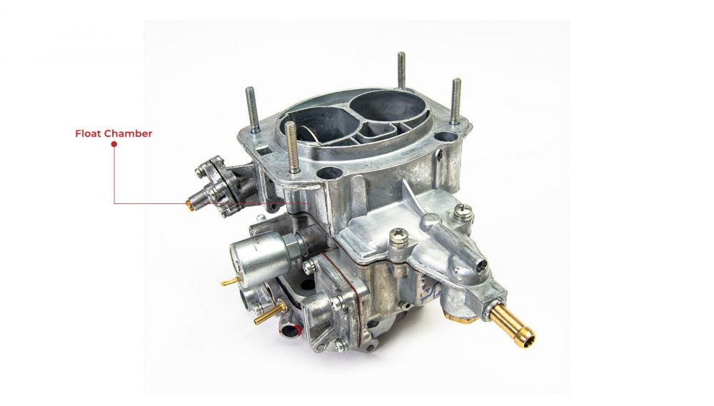
1. Float Chamber
The float chamber, also known as the fuel bowl, acts as a reservoir holding a constant supply of fuel at atmospheric pressure, ready for use by the carburetor. It’s a small container typically located beside the venturi. A key component within this chamber is the float, which, as its name suggests, floats on the fuel. As fuel enters the chamber, the float rises. When the fuel reaches a predetermined level, the float mechanism closes a needle valve, stopping the fuel supply. This clever system ensures a consistent fuel level, vital for proper carburetor operation. If the float malfunctions, often due to debris or damage, it can lead to fuel overflow, known as flooding, or fuel starvation, both detrimental to engine performance.
2. Float
The float is a small, buoyant component, typically made of plastic or brass, residing within the float chamber. Its primary function is to maintain a consistent fuel level in the chamber. It achieves this by being connected to a needle valve that controls the fuel inlet. As the fuel level rises, the float rises, eventually pushing the needle valve into its seat, thus cutting off the fuel supply. Conversely, as fuel is used and the level drops, the float descends, opening the needle valve to allow more fuel in. This continuous cycle ensures a stable fuel head for the jets to draw from, regardless of fuel consumption rate. A properly functioning float is crucial for preventing fuel starvation or flooding, both of which can severely impact engine performance and efficiency.
3. Choke Valve
The choke valve is a butterfly valve located at the air intake of the carburetor. Its primary function is to enrich the fuel-air mixture when starting a cold engine. When the engine is cold, fuel doesn’t vaporize as readily, requiring a richer mixture (more fuel, less air) for easier starting. Activating the choke valve, either manually or automatically, restricts airflow into the carburetor. This restriction increases the vacuum in the venturi, drawing more fuel into the intake manifold, creating the richer mixture needed for cold starts. Once the engine warms up, the choke valve should be gradually opened to restore the normal air-fuel ratio for efficient running. Leaving the choke engaged for too long can lead to excessive fuel consumption and engine fouling.
4. Throttle Valve
The throttle valve, also known as the butterfly valve, is positioned in the carburetor bore, downstream from the venturi and choke. It is directly connected to the accelerator pedal and controls the amount of air-fuel mixture entering the engine. When the accelerator pedal is pressed, the throttle valve opens wider, allowing more mixture into the engine cylinders, resulting in increased engine speed and power. Conversely, releasing the pedal closes the throttle valve, reducing the mixture flow and slowing the engine down. The throttle valve is essentially the primary control for engine power output, regulating the engine’s response to driver input.
5. Main Jet
The main jet is a precisely calibrated metering device that controls the fuel flow during mid to high engine speeds and loads. It’s essentially a small screw with a precisely sized orifice or opening. Fuel from the float chamber is drawn through the main jet and into the venturi due to the vacuum created by airflow. The size of the main jet orifice directly affects the amount of fuel delivered at higher throttle openings. A larger main jet allows more fuel to flow, resulting in a richer mixture, while a smaller jet restricts fuel flow, creating a leaner mixture. Selecting the correct main jet size is critical for achieving the optimal fuel-air ratio for performance and fuel efficiency under various driving conditions.
6. Jet Needle
The jet needle works in conjunction with the main jet to fine-tune fuel delivery across the mid-range throttle positions. It’s a tapered needle that sits inside the needle jet (or emulsion tube), which is positioned above the main jet. As the throttle valve opens, the jet needle is lifted out of the needle jet. The tapered shape of the needle progressively increases the annular space between the needle and the jet, allowing more fuel to flow. The position of the jet needle, often adjustable via a clip in some carburetors, allows for precise tuning of the fuel mixture in the crucial mid-throttle range, impacting throttle response and fuel economy during normal driving.
7. Slow Jet (Pilot Jet)
The slow jet, also known as the pilot jet or idle jet, is responsible for supplying fuel to the engine when it’s idling or running at very low speeds with the throttle valve nearly closed. Similar to the main jet, it’s a small, precisely sized orifice. When the throttle is closed, the vacuum in the venturi is minimal. The slow jet circuit utilizes engine vacuum from a different source, typically from behind the throttle valve, to draw fuel and air, creating a lean mixture suitable for idle conditions. A clogged slow jet is a common cause of rough idling or difficulty starting, as it disrupts the fuel supply at low engine speeds.
8. Piston Valve Screw and Pilot Screw
The piston valve screw and pilot screw are adjustment screws used to fine-tune the idle mixture and idle speed. The pilot screw typically adjusts the air-fuel mixture at idle by controlling the amount of air entering the slow jet circuit. Turning it in usually richens the mixture, while turning it out leans it. The piston valve screw, sometimes referred to as the idle speed screw, physically adjusts the resting position of the throttle valve when closed. By adjusting these screws, mechanics can achieve a smooth and stable idle, ensuring the engine runs correctly when no throttle is applied.
9. Main Nozzle (Emulsion Tube)
The main nozzle, often called the emulsion tube, is a critical component in the main jet circuit. It’s a tube with small holes along its length, positioned in the venturi. Fuel from the main jet flows into the bottom of the emulsion tube, and as air is drawn in through these small holes, it mixes with the fuel, creating an emulsified fuel-air mixture. This pre-atomization of the fuel enhances vaporization and improves combustion efficiency. The emulsion tube plays a significant role in the carburetor’s ability to deliver a well-mixed and easily combustible fuel-air charge to the engine.
10. Venturi
The venturi is a constricted section within the carburetor’s air passage. Its shape is designed based on the Bernoulli principle. As air flows through the venturi, its speed increases due to the narrowing passage, causing a drop in air pressure. This pressure drop (vacuum) is what draws fuel from the float chamber, through the jets and nozzles, and into the airstream. The venturi is fundamental to the carburetor’s operation, as it creates the necessary vacuum to meter and mix fuel with air. Different carburetor designs may employ single or multiple venturis to optimize airflow and fuel atomization across the engine’s operating range.
The Core Function of a Carburetor
The primary function of a car carburetor is to precisely mix air and fuel in the correct ratio to create a combustible mixture for the engine. This mixture needs to vary depending on engine speed, load, and temperature. The carburetor is designed to atomize the fuel, breaking it into tiny droplets that can readily vaporize and mix with air. This ensures efficient combustion in the engine cylinders, leading to optimal power output and fuel economy. The carburetor’s intricate system of jets, valves, and passages works in harmony to deliver the right fuel-air mixture under diverse driving conditions, from idling to full throttle.
How a Carburetor System Works
Carburetors operate based on the Bernoulli principle, which states that as the speed of a fluid (in this case, air) increases, its pressure decreases. Here’s a simplified breakdown of how it works:
- Air Intake: As the engine’s pistons move downwards on the intake stroke, they create a vacuum, drawing air into the engine through the carburetor.
- Venturi Effect: This incoming air is forced to pass through the venturi, a narrowed section in the carburetor bore. The venturi increases the airspeed and reduces the air pressure.
- Fuel Draw: The low pressure in the venturi creates a pressure difference compared to the atmospheric pressure in the float chamber. This pressure difference forces fuel from the float chamber, through the jets and nozzles, and into the venturi.
- Mixing and Atomization: As fuel enters the venturi, it’s broken into tiny droplets and mixed with the fast-moving air stream, creating an atomized fuel-air mixture.
- Mixture Delivery: This combustible mixture then flows past the throttle valve and into the intake manifold, from where it’s distributed to the engine cylinders for combustion.
- Throttle Control: The driver controls the amount of mixture entering the engine by manipulating the throttle valve via the accelerator pedal, thereby regulating engine speed and power.
Essential Carburetor Care Steps
To ensure your carburetor functions optimally and to prolong its lifespan, regular maintenance is crucial. Here are key steps for carburetor care:
1. Clean the Air Filter
Start by cleaning the air filter. A dirty air filter restricts airflow to the carburetor, leading to a rich fuel mixture and reduced engine performance. Remove the air filter element from its housing, typically located on top of or near the carburetor. If it’s a paper filter, gently tap it to remove loose dirt and debris. For more thorough cleaning, use compressed air to blow out dirt from the inside out. If your air filter is made of foam, wash it with mild soap and water, rinse thoroughly, and allow it to dry completely before reinstalling. Regular air filter cleaning or replacement is a simple yet effective way to maintain carburetor efficiency.
2. Disassemble Carburetor Components
For a more in-depth cleaning, you’ll need to disassemble the carburetor. Before starting, ensure the engine is cool and disconnect the fuel line. Carefully remove the carburetor from the intake manifold, taking note of the positions of vacuum lines and linkages. Once removed, place the carburetor on a clean workbench. Using appropriate screwdrivers and wrenches, carefully disassemble the carburetor components, such as the float bowl, jets, float, and needles. It’s helpful to take pictures as you disassemble to aid in reassembly. Keep all small parts organized in a tray or container to avoid losing them.
3. Clean Carburetor Parts Thoroughly
With the carburetor disassembled, thoroughly clean all components. Use carburetor cleaner spray to dissolve varnish and deposits. Pay special attention to jets and small passages, ensuring they are clear of obstructions. Fine wires or specialized carburetor cleaning tools can be used to carefully clean jet orifices. For stubborn deposits, you can soak metal parts in carburetor cleaner. Avoid using harsh abrasives that could damage delicate components or alter jet sizes. After cleaning, rinse all parts with clean carburetor cleaner or solvent and allow them to air dry completely.
4. Reassemble and Adjust
Once all parts are clean and dry, carefully reassemble the carburetor, referring to your disassembly pictures or a repair manual if needed. Ensure all gaskets and seals are in good condition and replace them if necessary to prevent leaks. After reassembly, reinstall the carburetor onto the intake manifold and reconnect fuel and vacuum lines. Start the engine and allow it to warm up. Adjust the idle speed and idle mixture screws to achieve a smooth and stable idle, following your vehicle’s service manual specifications. Fine-tuning may be required to optimize performance after cleaning.
By understanding the components, functions, and maintenance of your car’s carburetor, you can ensure its longevity and contribute to the overall smooth and efficient operation of your vehicle. Regular care and timely attention to carburetor issues will keep your car running reliably for years to come.