Like many, you might drive your car daily without fully grasping what’s happening under the hood. Beyond routine tasks like changing air filters or oil, the intricate workings of a vehicle can seem like a mystery. However, gaining a fundamental understanding of your car’s components is not only empowering but also practical. Whether it’s deciphering mechanic jargon or simply satisfying your curiosity about the technology you rely on, learning about basic car parts is a worthwhile endeavor. This guide will walk you through the essential components, using a Basic Car Parts Diagram as our roadmap, to illuminate the inner workings of your automobile.
Why a Basic Car Parts Diagram is Your Best Starting Point
A basic car parts diagram is more than just a visual aid; it’s your entry point to automotive literacy. Imagine it as an anatomical chart for your car, revealing the names and locations of crucial components. Before diving into complex mechanics, a diagram provides a foundational understanding of what’s what. It helps you:
- Identify Key Components: Visually recognize and name the major parts of your car, especially the engine.
- Understand Spatial Relationships: See how different parts are connected and positioned relative to each other.
- Communicate Effectively with Mechanics: Use correct terminology when discussing car issues, leading to clearer communication and potentially better service.
- Grasp Basic Functionality: Begin to understand how these parts work together to make your car move.
- Build Confidence for Further Learning: A basic understanding encourages deeper exploration into specific systems and repair procedures.
Think of a basic car parts diagram as the legend to the map of your car’s inner world. Let’s start our exploration with the engine, the heart of your vehicle, guided by our diagram.
Decoding the Internal Combustion Engine with a Diagram
The engine, often referred to as the internal combustion engine, is where the magic of motion begins. The term “internal combustion” itself tells us that the energy is generated by burning fuel inside the engine. This combustion process creates the force that moves pistons, ultimately propelling your car forward.
To appreciate this, consider the historical context. While steam engines (external combustion engines) might seem like predecessors, internal combustion engines actually came first. Early versions in the 16th century used gunpowder, though inefficiently. It was Jean Joseph Etienne Lenoir in 1860 who patented a more practical engine using natural gas. Building on this, Nicolaus August Otto developed the four-stroke engine in 1864, the foundation of modern car engines.
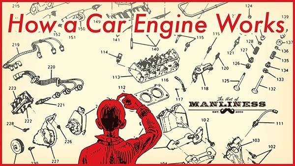
Let’s use a basic car parts diagram to visualize the key components of this ingenious system.
This diagram illustrates the complexity within what might seem like a solid block of metal. Each part plays a vital role in the combustion process, converting fuel into motion. Let’s dissect the anatomy of the engine, part by part, using our basic car parts diagram as a reference.
Exploring the Anatomy of a Car Engine: A Diagram-Guided Tour
To understand the engine’s operation, we need to familiarize ourselves with its key components. Refer to a basic car parts diagram as we go through each part.
1. Engine Block (Cylinder Block): The Foundation
The engine block, or cylinder block, is the structural backbone of the engine. Typically made from aluminum alloy or iron, it houses the cylinders – the hollow tubes where pistons move. The number of cylinders often indicates engine power (e.g., V6, V8). The block also contains passages for oil and coolant circulation.
V6 vs. V8: Cylinder Configuration Explained
These designations refer to the arrangement and number of cylinders. Inline engines have cylinders in a straight row. Flat engines (like “flat-four”) have horizontally opposed cylinders. Engines with more than four cylinders often use a “V” configuration, with two banks of cylinders. A V6 has six cylinders in a V shape, and a V8 has eight.
2. Combustion Chamber: Where Power is Born
This is where the magic happens. The combustion chamber is the space where fuel, air, compression, and spark combine to create controlled explosions. It’s formed by the cylinder walls, the piston top (floor), and the cylinder head (ceiling).
3. Cylinder Head: Sealing the Combustion
The cylinder head sits atop the engine block, sealing the cylinders. It has indentations for combustion space and mounting points for intake/exhaust valves, spark plugs, and fuel injectors. A head gasket ensures a tight seal between the cylinder head and block.
4. Piston: The Moving Force
Pistons are cylindrical components that move up and down within the cylinders. The force from combustion pushes the piston down, which then rotates the crankshaft. Pistons are connected to the crankshaft via connecting rods. Piston rings, located in grooves on the piston, seal the combustion chamber and prevent oil leakage.
5. Crankshaft: Converting Linear to Rotational Motion
The crankshaft is crucial for transforming the piston’s up-and-down motion into the rotational motion that drives the wheels. It sits at the bottom of the engine block in the crankcase. The crankshaft connects to belts that power other components and to the drivetrain that transmits power to the wheels. The crankcase also includes the oil pan, which stores engine oil, and an oil pump for lubrication.
6. Camshaft: The Engine’s Brain
The camshaft is the engine’s timing coordinator. It works with the crankshaft via a timing belt or chain to precisely control the opening and closing of intake and exhaust valves. Lobes on the camshaft dictate valve timing. Inline engines often have a single camshaft, while V-engines may have one or more per cylinder bank.
7. Timing System: Synchronization is Key
The timing belt or chain synchronizes the crankshaft and camshaft, ensuring valves open and close at the correct moments relative to piston position. Proper timing is essential for engine operation.
8. Valvetrain: Controlling Air and Exhaust Flow
The valvetrain, mounted on the cylinder head, manages the valves. It includes valves, rocker arms, pushrods, and lifters.
9. Valves: Intake and Exhaust Gatekeepers
Intake valves allow the air-fuel mixture into the combustion chamber. Exhaust valves release combustion gases. Most cars have at least one intake and one exhaust valve per cylinder; performance engines often have multiple valves for improved breathing.
10. Rocker Arms: Valve Levers
Rocker arms are levers that interact with the camshaft lobes. As the camshaft rotates, the lobes move the rocker arms, which in turn open and close the valves.
11. Pushrods/Lifters: Transmitting Camshaft Motion
In some engines (overhead valve engines), pushrods and lifters transmit the camshaft’s motion to the rocker arms, as the camshaft isn’t directly above the valves.
12. Fuel Injectors: Delivering the Fuel
Fuel injectors spray fuel into the combustion chamber. Modern cars use fuel injection instead of carburetors. Direct injection sprays fuel directly into the cylinder, while port injection sprays it into the intake manifold. Throttle body injection is an older system with a single injector.
13. Spark Plug: Igniting the Mixture
The spark plug, located above each cylinder, provides the spark to ignite the compressed air-fuel mixture, initiating combustion and the power stroke.
This detailed basic car parts diagram provides a clearer picture of how these components are arranged and interconnected within the engine. Understanding these parts is the first step to understanding how they work together in the four-stroke cycle.
The Four-Stroke Cycle: The Engine’s Rhythm Visualized in a Diagram
Now that we’ve identified the key players using a basic car parts diagram, let’s see how they orchestrate movement in the four-stroke cycle. This cycle, occurring in each cylinder, is the fundamental process that powers your car.
As shown in the diagram, the four strokes are:
- Intake Stroke: The piston moves down, drawing a mixture of air and fuel into the cylinder through the open intake valve.
- Compression Stroke: Both intake and exhaust valves close. The piston moves up, compressing the air-fuel mixture.
- Combustion (Power) Stroke: The spark plug ignites the compressed mixture. The resulting explosion forces the piston down, generating power.
- Exhaust Stroke: The exhaust valve opens. The piston moves up, pushing the exhaust gases out of the cylinder.
This cycle repeats continuously in each cylinder, thousands of times per minute, creating the sustained power that drives your vehicle.
Conclusion: From Diagram to Driving Understanding
By using a basic car parts diagram as our guide, we’ve journeyed into the heart of your car and uncovered the fundamental components and processes that make it move. While this is a foundational overview, it provides a solid starting point for further exploration.
Take some time to look under the hood of your car and try to identify the parts we’ve discussed, using a basic car parts diagram as your reference. For deeper learning, resources like “How Cars Work” offer comprehensive explanations in an accessible manner. Understanding your car, even at a basic level, empowers you as a driver and enhances your appreciation for the marvel of automotive engineering.