Canards, often referred to as dive planes or dive plates, are small wing-like attachments positioned on the front bumper of vehicles. These aerodynamic components are characterized by a lack of standardization in their shape, size, curvature, and mounting locations, making them somewhat enigmatic. The actual effect of canards on a vehicle’s performance is a complex interplay of various factors and perspectives.
Verus Engineering offers a concise explanation: “Dive planes, also referred to as canards, allow you to shift the aero balance forward, possibly aiding you and your setup in balancing out a large rear wing or diffuser. Dive planes also help seal the sides of the car and help evacuate air from the wheel well, further reducing lift and drag in some cases.”
This description hints at the nuanced nature of canards – they might be beneficial, but their effectiveness isn’t guaranteed. In simpler terms, “Sometimes Canard Car Parts will make your car faster.”
Conversely, canards have the potential to hinder performance. Being located at the front edge of the vehicle, they influence the airflow across all subsequent areas, including the car’s sides, underbody, wake, and crucially, the rear wing. This interference can sometimes be detrimental to overall aerodynamic efficiency.
The Aerodynamics of Canard Car Parts
Unlike airfoils, canards typically lack a distinct airfoil shape. They generate downforce primarily through pressure differences rather than suction. In his book Race Car Aerodynamics, Joseph Katz analyzes dive plates, assigning them a lift coefficient (Cl) of 0.03 and a drag coefficient (Cd) of 0.01. This 3:1 lift-to-drag ratio is reminiscent of a spoiler’s performance, which aligns with the general understanding of canard functionality.
Canards can be strategically employed in specific scenarios:
- Vehicles with Exposed Front Tires: For older car designs or vehicles where the front tires are exposed to direct airflow (like the Mazda Miata), canards can effectively deflect air away from the tires. This reduces drag and aerodynamic disturbances caused by the rotating wheels.
- Cars with Flat Underbodies: Canards can contribute to sealing the sides of the vehicle by generating a vortex. This vortex can enhance the effectiveness of a flat underbody in producing downforce by preventing air from spilling around the sides and disrupting the low-pressure zone underneath.
- Splitter Equipped Cars: When a front splitter is installed without additional side aerodynamic elements like spats, strategically placed canards, mounted low on the bumper fascia, can be advantageous. They aid in extracting air sideways, optimizing the splitter’s performance. This interaction between canards and splitters is a key area for detailed exploration.
DIY Canard Car Part Installation
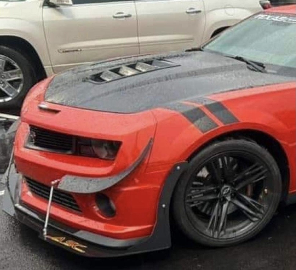
The Hyundai Veloster N, with its complex bodywork featuring vents, curves, and sharp angles, presents a unique challenge for canard installation. The vehicle’s design inherently limits the options for canard size, shape, and mounting locations. Essentially, the existing body lines dictate the parameters for canard integration.
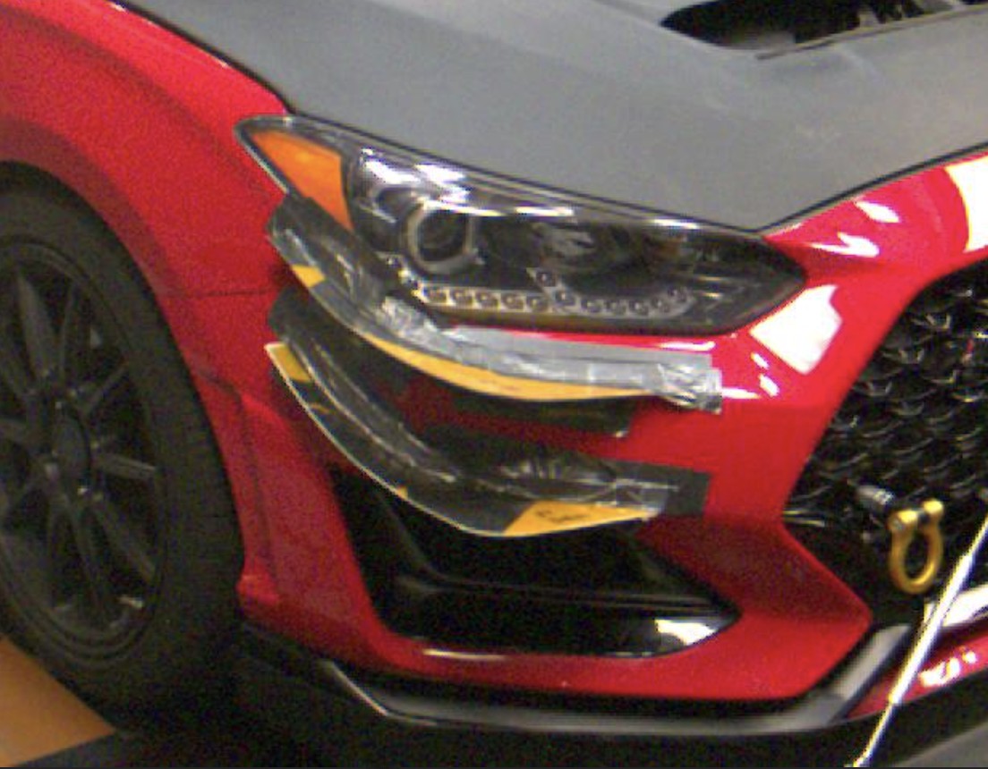
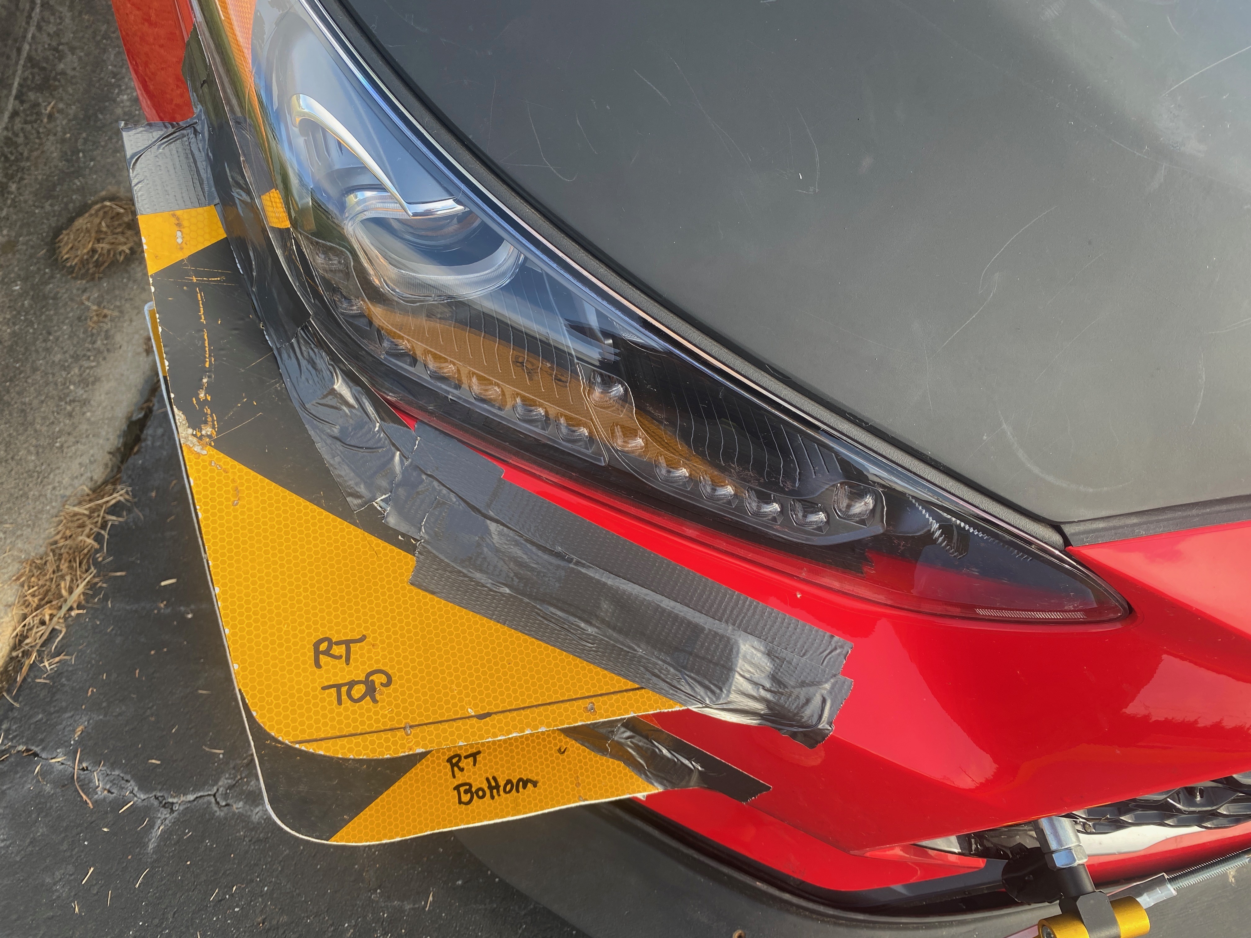
Considering these constraints, only three logical positions emerged for mounting canards on the Veloster N. For a cost-effective DIY approach, aluminum street signs, sourced from a local recycler, were utilized as the material. These were shaped and curved to conform to the bumper fascia and fit within the available spaces. Importantly, all canards were fabricated to be identical in shape and curvature to ensure consistency in testing.
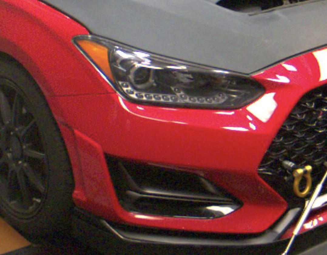
The uppermost canard was positioned just below the headlight. The headlight design incorporates a flat area both beneath and in front of it. Placing a canard in this location effectively expands the planform area without requiring significant modification. Increased planform area is generally beneficial as it provides more surface for pressure to act upon, potentially increasing downforce.
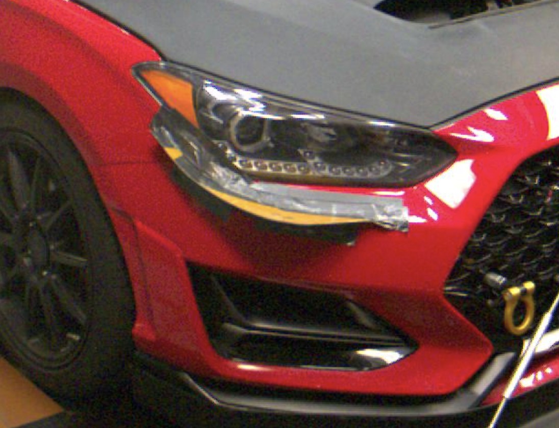
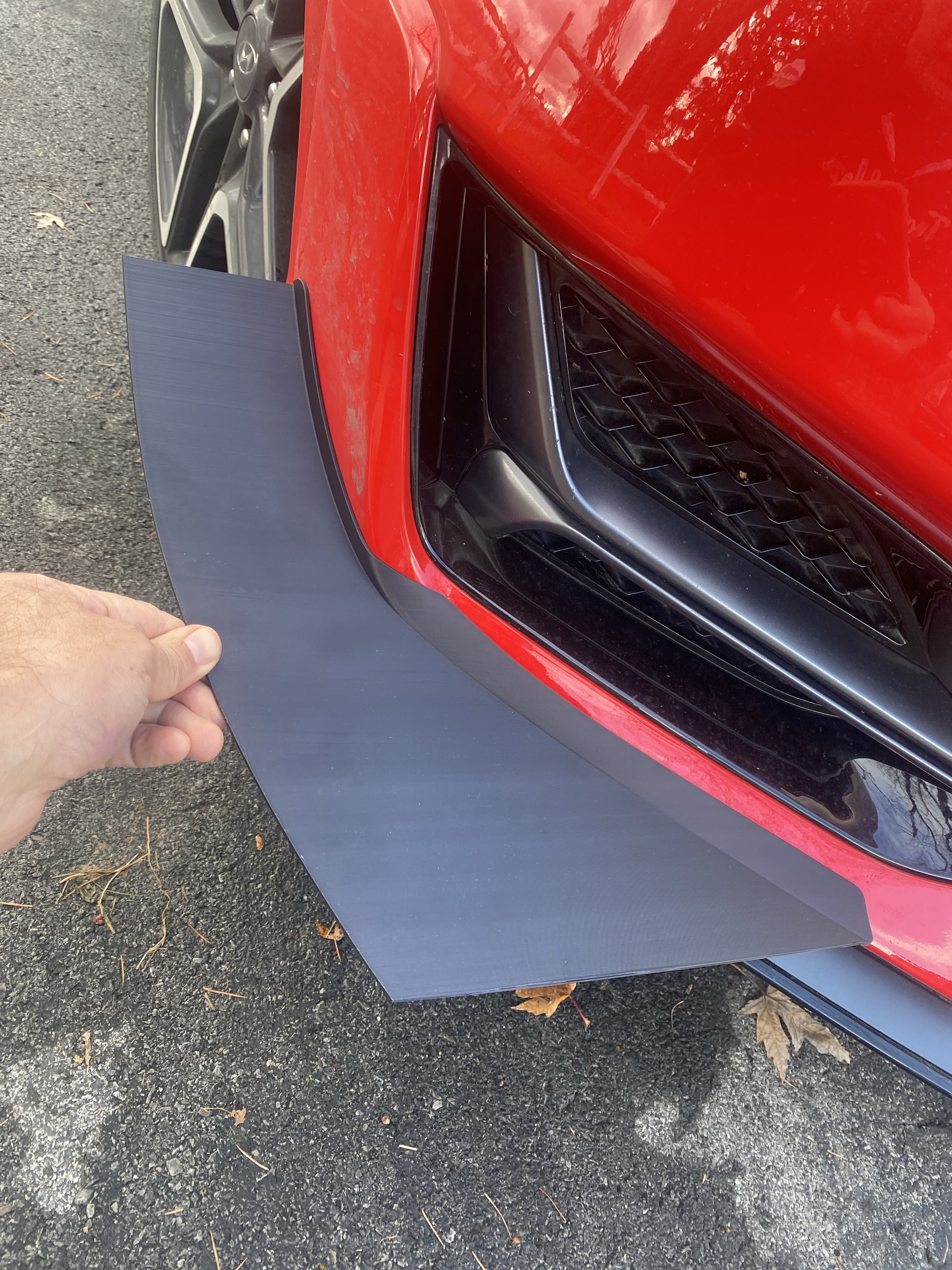
A second canard was positioned 5 inches below the top one, situated atop the air curtain duct on each side of the car. This height was dictated by the vehicle’s design, as lower placement was not feasible due to the duct’s location. Notably, many aerodynamic companies commonly position canards in this general vicinity, suggesting its potential effectiveness.
Finally, a third canard was placed as low as possible on the bumper fascia. This placement decision was influenced by expert advice during wind tunnel testing, highlighting the value of professional insight in aerodynamic optimization.
Wind Tunnel Test Data and Analysis
The wind tunnel tests were conducted with identical canards in terms of size and shape. The primary variable under investigation was canard location: top, middle, and bottom positions. It’s important to note that the test vehicle was also equipped with a splitter and a rear wing, as canards interact dynamically with these aerodynamic elements.
In the data table, front downforce is presented as a positive value, while rear downforce is negative, reflecting the seesaw effect inherent in aerodynamic adjustments. Changes at the front can influence downforce at the rear. Furthermore, turbulence generated by the canards could potentially impact the effectiveness of the rear wing. Total downforce is the sum of front and rear downforce values, and this is crucial when evaluating drag.
Drag measurements are also provided, and dividing total downforce by drag yields the Lift-to-Drag (L/D) ratio, a measure of aerodynamic efficiency. A higher L/D ratio indicates greater downforce for a given amount of drag. The top canard configuration demonstrated the highest efficiency at 3.91:1. The final column, HP, represents the horsepower consumed by drag from the canards at 100 mph.
| Downforce @ 100 mph | Drag |
|---|---|
| Front | Rear |
| No canards | 0.01 |
| Top only | 15.18 |
| Mid only | 11.13 |
| Top and mid | 26.30 |
| Bottom only | 85.61 |
| Top and bottom | 100.79 |
The top-mounted canard exhibited the highest efficiency, likely due to its position below the headlight, leveraging the additional planform area of the bodywork to enhance its effective surface area.
The middle canard, despite having the same drag as the top canard, generated less downforce. Its L/D ratio of 2.8:1 closely aligns with Katz’s cited values. While canards are frequently placed in this middle location by manufacturers, the data suggests it’s the least effective among the tested positions.
Combining the top and middle canards resulted in an additive effect, meaning their combined performance was essentially the sum of their individual contributions. There was no evidence of synergistic interaction to produce disproportionately greater downforce. This raises questions about the common practice of mounting canards in pairs.
The bottom-mounted canard yielded a remarkable outcome, generating over 700% more downforce compared to the middle canard, despite being only 8 inches lower. Drag also increased significantly, but this trade-off is often acceptable given the substantial downforce gain.
Combining the top and bottom canards aimed to merge the top canard’s superior L/D ratio with the bottom canard’s high downforce. This configuration produced over 100 lbs of front downforce, which, when balanced with increased rear downforce, would significantly enhance overall grip.
Discussion and Key Insights
Initial expectations for canard performance were modest, and they are sometimes dismissed as purely aesthetic modifications. However, the wind tunnel tests revealed their significant potential. The bottom canard position, in particular, proved to be unexpectedly effective, underscoring the importance of empirical testing and expert guidance in aerodynamic development.
Canards, lacking a true airfoil profile, operate primarily through pressure generation, not suction like wings. Theoretical limits suggest a maximum lift coefficient of around 1.0 for pressure-based downforce. Given that canard surface area and angle of attack were consistent across all positions, the significant downforce variation is not attributable to the canard itself.
The substantial downforce gain with the bottom canard suggests a suction-based mechanism, primarily involving the front splitter. The canard likely facilitates air extraction from the wheel wells and/or the sides of the splitter, thereby amplifying suction beneath the splitter and generating considerable downforce.
This enhanced downforce from the bottom canard is accompanied by increased drag. While drag is an inherent consequence of downforce generation, the bottom canard exhibited a less favorable downforce-to-drag ratio compared to the higher positions.
One possible explanation for the increased drag is the generation of a stronger vortex by the bottom canard. Vortex formation requires energy, and a more powerful vortex typically results in greater drag. Alternatively, canards might inherently be a less efficient downforce generation method, with drag increasing disproportionately to downforce gains. Regardless of the precise mechanism, canard height emerges as a critical factor in their performance.
Canard designs sometimes incorporate endplates or vertical outer edges. These features could potentially enhance local downforce generation by better containing pressure on the canard’s upper surface. However, for bottom-mounted canards, the primary objective might be to generate a strong vortex off the outer edge to enhance underbody suction, potentially making endplates less desirable in this specific application. Further research is needed to explore these design variations.
It is crucial to recognize that the presented downforce figures are specific to the test vehicle (Veloster N) and its aerodynamic configuration (splitter and wing). Canard performance is highly sensitive to vehicle-specific factors. The key takeaway from this testing is the demonstrated significance of canard height as a performance variable. However, numerous other parameters, including angle of attack, size, shape, fore-aft position, and wicker edge design, remain to be investigated.
In conclusion, while initially skeptical, wind tunnel testing has revealed the potential of canard car parts to enhance aerodynamic performance. A key insight from aerodynamicist AJ Hartman is that properly implemented canards have consistently improved the L/D ratio across various tested vehicles. However, achieving these benefits requires expertise in canard placement and angle adjustment. For enthusiasts opting for aftermarket canards based primarily on aesthetics, performance gains are far from guaranteed and may be highly variable.
| If you enjoyed reading this article, check out my wind tunnel report. It’s over 50 pages of similar data, but goes over many more pieces of aero, and to a much greater depth. |
|---|