Many drivers operate their vehicles daily without giving much thought to the intricate machinery beneath the hood. The engine, often perceived as a mysterious black box, is in fact a marvel of engineering composed of numerous interconnected parts working in harmony. For those aiming to move beyond basic car operation and delve into the mechanics that power their ride, understanding the anatomy of a car engine is a crucial first step. This guide will break down the Labeled Car Engine Parts, offering a clear and comprehensive overview for anyone from the curious car owner to the budding mechanic.
A Brief History of the Internal Combustion Engine
Before diving into the labeled car engine parts, it’s insightful to understand the historical context of this vital piece of technology. The internal combustion engine, the heart of most modern vehicles, is named so because fuel and air combust within the engine itself, generating the force needed to propel the car. This contrasts with external combustion engines, like steam engines, where fuel is burned externally to heat water and produce steam that drives the machinery.
Interestingly, the concept of internal combustion predates the widespread use of steam engines. Early iterations emerged as far back as the 16th century, utilizing gunpowder to drive pistons. These early engines, known as atmospheric engines, were inefficient and soon overshadowed by the advancements in steam engine technology during the 17th century.
It wasn’t until 1860 that a practical internal combustion engine resurfaced, thanks to Jean Joseph Etienne Lenoir. His engine used natural gas ignited by a flame, though it still lacked efficiency. Further refinement came in 1864 from Nicolaus August Otto and Eugen Langen, who built upon Lenoir’s work. Otto’s later innovation, the four-stroke engine, patented in 1876, revolutionized engine design. This foundational four-stroke principle remains the cornerstone of car engines today, a testament to its enduring effectiveness.
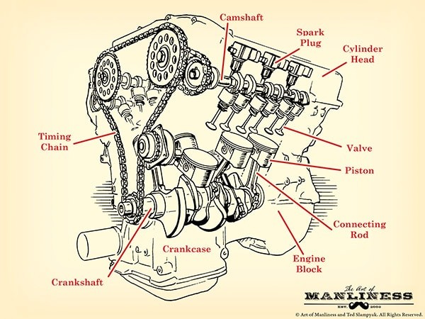
Anatomy of a Car Engine: Labeled Car Engine Parts
To truly grasp how an engine functions, familiarity with its components is essential. Below is a breakdown of key labeled car engine parts, explaining their role within the engine system.
Engine Block (Cylinder Block)
The engine block, also known as the cylinder block, serves as the structural backbone of the engine. Typically constructed from aluminum alloy or iron, it houses the cylinders, which are cylindrical cavities where pistons move. The number of cylinders often dictates engine power; more cylinders generally mean a more powerful engine. Beyond housing cylinders, the engine block incorporates passages for coolant and oil circulation, essential for temperature regulation and lubrication.
Understanding Engine Configurations: V6 and V8
Engine designations like “V6” or “V8” refer to the cylinder arrangement and count. Inline engines, common for four-cylinder setups, position cylinders in a straight row above the crankshaft. “Flat four” engines also use four cylinders, but arrange them horizontally in two banks.
Engines with more than four cylinders often adopt a V-shape. Here, cylinders are split into two banks forming a “V” shape. A V6 engine has six cylinders arranged in two banks of three, while a V8 engine features eight cylinders across two banks of four.
Combustion Chamber
The combustion chamber is where the engine’s power is generated. This is the space where fuel and air mix, are compressed, and ignited, causing an explosion that drives the pistons. The combustion chamber is formed by the cylinder walls, the piston top, and the cylinder head.
Cylinder Head
Positioned above the engine block, the cylinder head seals the top of the cylinders, forming the ceiling of the combustion chamber. It’s typically made of metal and features indentations to optimize combustion space. A head gasket ensures a tight seal between the cylinder head and engine block, preventing leaks. The cylinder head also serves as a mounting point for intake and exhaust valves, spark plugs, and fuel injectors.
Piston
Pistons are cylindrical components that move vertically within the cylinders. Shaped somewhat like inverted cans, they are driven downwards by the force of combustion in the chamber. This linear motion is then converted into rotational motion. Each piston connects to the crankshaft via a connecting rod, also known as a con rod, and a piston pin facilitates the connection to the connecting rod. Connecting rod bearings link the connecting rod to the crankshaft.
Pistons are equipped with piston rings set in grooves around their circumference. These rings, made of iron, are crucial for sealing the combustion chamber and managing oil. Compression rings, located at the top, press against the cylinder walls to maintain combustion chamber pressure. Oil rings, positioned lower, prevent oil from entering the combustion chamber from the crankcase and scrape excess oil off cylinder walls.
Crankshaft
The crankshaft is a vital component that converts the reciprocating motion of the pistons into rotary motion, which ultimately powers the vehicle’s wheels. It sits lengthwise within the engine block, typically near the bottom. At the front, it links to belts that drive the camshaft and ancillary components. At the rear, it connects to the drivetrain, transmitting power to the wheels. Oil seals at each end prevent oil leakage.
The crankshaft operates within the crankcase, located below the cylinder block, which protects it and the connecting rods. The lower part of the crankcase is the oil pan, the engine’s oil reservoir. Inside the oil pan, an oil pump circulates oil through a filter and then to critical parts like the crankshaft, connecting rod bearings, and cylinder walls for lubrication. The oil then returns to the oil pan, repeating the cycle.
Balancing lobes along the crankshaft act as counterweights, minimizing vibrations from rotation. Main bearings provide smooth contact surfaces between the crankshaft and engine block, allowing for free rotation.
Camshaft
The camshaft is often referred to as the “brain” of the engine because it precisely controls the timing of valve operation in coordination with the crankshaft. Linked to the crankshaft by a timing belt or chain, the camshaft ensures intake and exhaust valves open and close at the correct moments for efficient engine performance. Egg-shaped lobes along the camshaft dictate valve timing.
In inline engines, a single camshaft usually manages both intake and exhaust valves. V-shaped engines may use one or two camshafts per cylinder bank. Dual camshaft configurations, especially in V-engines, allow for more precise valve control, enhancing engine breathing and performance.
Timing System
The timing system, typically a timing belt or chain, synchronizes the crankshaft and camshaft rotation. This precise synchronization is critical; it ensures that valve opening and closing events are perfectly aligned with piston movement. If the timing is off, for example, if the timing chain slips, the engine will malfunction or fail to start.
Valvetrain
The valvetrain is the system that controls the valves, mounted in the cylinder head. It includes valves, rocker arms, pushrods, and lifters, all working together to manage the flow of gases into and out of the combustion chamber.
Valves
Engines employ two types of valves: intake and exhaust valves. Intake valves allow the air-fuel mixture to enter the combustion chamber for combustion. Exhaust valves allow the combustion byproducts to exit the chamber.
Typically, engines have at least one intake and one exhaust valve per cylinder. High-performance engines often utilize multi-valve configurations, such as four valves per cylinder (two intake and two exhaust), to improve engine breathing and efficiency. Some engines may even use three valves per cylinder (two intake, one exhaust).
Rocker Arms
Rocker arms are levers that interact with the camshaft lobes. As the camshaft rotates, the lobes push on one end of the rocker arm, causing the other end to press down on the valve stem, opening the valve. This see-saw action precisely controls valve opening and closing.
Pushrods/Lifters
In engines with overhead valves, pushrods and lifters are used to transfer motion from the camshaft to the rocker arms, as the camshaft is not directly above the valves. Lifters, also known as valve lifters or tappets, sit between the camshaft and pushrods. They ensure that the pushrods correctly transmit the camshaft’s motion to the rocker arms.
Fuel Injectors
Fuel injectors deliver fuel into the engine’s cylinders for combustion. Modern cars primarily use fuel injection systems instead of carburetors, which were common in older vehicles. There are three main types of fuel injection:
- Direct Fuel Injection: Injects fuel directly into each cylinder’s combustion chamber for precise control and efficiency.
- Ported Fuel Injection: Sprays fuel into the intake manifold, just outside the intake valve. The air-fuel mixture then enters the cylinder when the valve opens.
- Throttle Body Fuel Injection: A single injector feeds fuel into the throttle body where it mixes with air before being distributed to the cylinders via the intake manifold.
Spark Plug
Located above each cylinder, the spark plug initiates combustion. It generates an electrical spark that ignites the compressed air-fuel mixture in the combustion chamber, starting the power stroke.
The Four-Stroke Cycle
Understanding the labeled car engine parts is only part of the picture. To see how these parts work together, it’s crucial to understand the four-stroke cycle, the sequence of events that produces power in most car engines.
This cycle, repeated continuously in each cylinder, drives the engine and, consequently, the vehicle.
-
Intake Stroke: The piston moves down, creating a vacuum in the cylinder. The intake valve opens, allowing the air-fuel mixture to be drawn into the combustion chamber.
-
Compression Stroke: The intake valve closes, and the piston moves upwards, compressing the air-fuel mixture. This compression increases the mixture’s temperature and readies it for combustion.
-
Combustion (Power) Stroke: As the piston reaches the top of its stroke, the spark plug ignites the compressed mixture. The resulting explosion forces the piston downwards, generating power. This is the only stroke that produces power.
-
Exhaust Stroke: The exhaust valve opens, and the piston moves upwards, pushing the burnt exhaust gases out of the cylinder. The cycle then restarts with the intake stroke.
This four-stroke cycle, happening hundreds or thousands of times per minute across all cylinders, is what propels your vehicle.
Conclusion
Understanding labeled car engine parts and how they function within the four-stroke cycle demystifies the engine and empowers car owners with valuable knowledge. While this overview provides a foundational understanding, further exploration into each component and system can deepen your expertise. By familiarizing yourself with these fundamental aspects of engine mechanics, you gain a greater appreciation for the engineering marvel that powers your daily commute.